The lower bridgedeck floor was raised after the hulls were turned and the major structural port-starboard frames were built.
The prebuilt bridgedeck was then single-handedly raised and anyone who has tried to lift 250kg (in a flat sheet 10m x 3.5m) will understand the challenge faced. As it was a weekday, all our friends were working. We can say that with one person, plenty of scrap wood, two tables, some scaffolding and a hydraulic jack, it can be raised single-handed.
This was then resined and glassed into place.
Our main entry door frame was then built once the lower bridgedeck was in place. That a great achievement.
For the first time, we were actually working off the ground - on a boat floor. This definitely provided an incentive as you could now picture being on the water. We were lucky enough to have Peter (the EASY designer) build the lower bridgedeck floor for us.
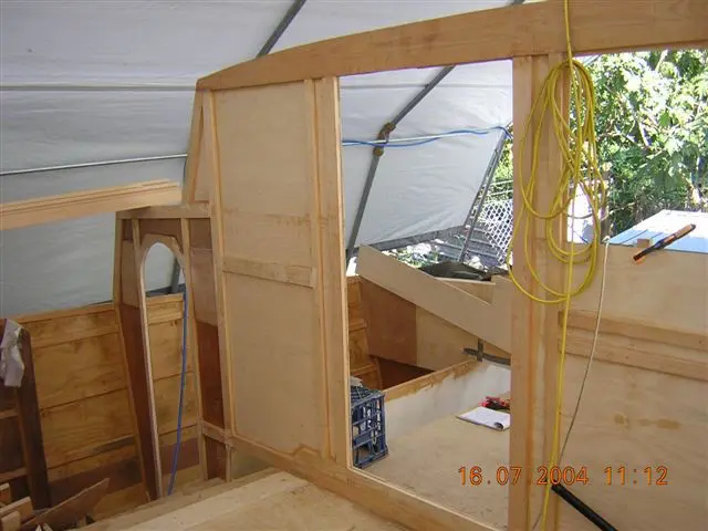
Lower bridgedeck and door frame in place
Commonly called 'the deck', the upper bridgedeck is the most used part of the yacht.
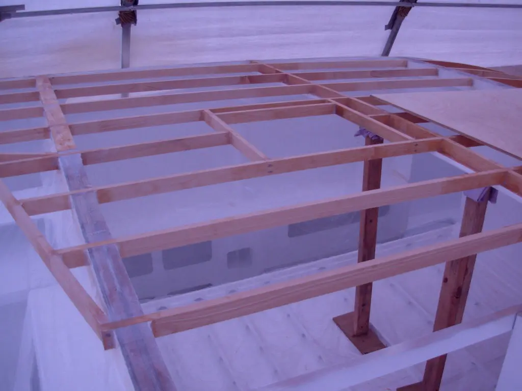
The first project was to cut the notches to take the fore aft deck timbers called ‘Stringers’. In one of those magic-thought-days, we had decided to pre-cut them prior to painting, and we are very glad we did. Keeping the sawdust off our newly painted surfaces was the main objective and also preventing accidental drops of tools on these surfaces too.
Next was to install braces below deck level to prop the soon to be installed frames and plywood. Following this came the trial and cutting of the timber lengths to run fore / aft below the deck floor. With the length of the 11.6m Easy, the timber lengths used for the stringers strips were not long enough to run in a single piece from the fore to the aft, which meant time for scarfing.
Finally, the plywood sheets were set and cut and before you knew it, the interior really took shape. All surfaces were then heavily resined to seal from the elements.
Upper bridgedeck framing (Note: we chose to paint internally before building the upper bridgedeck!!!)
The streamline shape of the catamaran turret does in itself provide a challenge or two to the uninitiated such as ourselves. Try twisting a single plywood sheet both horizontally and vertically. It cannot be done...or so we thought.
We found this in the cutting of the sides for the turret, arching over the deck and then also peeling inward from the forward top sections inward.
Next came the securing of the plywood to form the underside of the turret roof. Before this could be done, four lengths of raw garden edging (5m in length and 19mm x 200mm) were purchased to be used as the frame on which the turret would finally be built. These lengths were all cut at the same arc as the top of the 'plans - door-frame', to form the final arc of the turret roof. These were then braced in place by strong pieces of vertical timber to the lower bridgedeck. Having four frames now in place allowed for the construction to start.
The intention with our construction was to extend the turret roof to the rear of the yacht to provide for additional shelter. As this is not part of the plans, we built blind and reinforced some of the turret stringers with 68mm x 19mm (thicker than those in the plans).
To provide additional support, two solid 68mm x 42mm sections of timber were glued and screwed vertically against the back frame. As will be seen later, the strength here would be twofold, being also used in strengthening the davits.
A serious approach had now to be taken toward our electrical requirements, because the solar wiring (as well as the base for its securing), had to be installed before the turret top could be completed.
> How many panels?
> How many Watts per panel?
> What sort of ‘Smart Charger’ would we buy?
> What is a ‘Smart Charger’ and where does it have to go?
This is discussed in more detail in our 'Building Books' with charts and planning tools. Another real help here are the electrical bibles written by Nigel Calder, making real practical sense of any sailboat electrical set-up, including solar installation considerations.
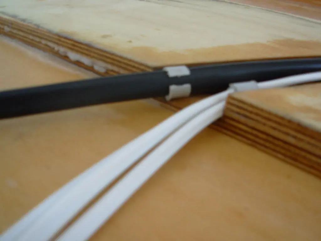
The solar wiring and internal roof lighting cables are needed to be installed at this early stage. We still continue to refer to his volumes while on the water, real gems.
Armed with our new found electrical information and cabling installed, it was onto the top panels and what a joy. The extended roof structure had worked extremely well and appeared to be the envy of a few other builders.
Careful consideration was needed with the cockpit entry step area, as cut-outs would be needed to accommodate the turret extension, or it's your head that would bear the brunt when stepping into the cockpit area.
Then it was onto the forward windows. This also presented a challenge or two, successfully overcome. We came up with some great ideas, especially considering that these windows are normally home-made and always leak. One has been known to build the centre forward window to find that once the mast was installed, the window could not be opened...just a tip.
Turret solar and 12vDC wiring, before top skin installation.